The Rewritable MiniDisc System
Tadao YoshidaAdvanced Development Laboratories
Sony Corporation, Tokyo, Japan
Reprinted from the Proceedings of the IEEE,USA
vol. 82 no. 10 pp.
1492-1500, OCT 1994.
Invited Paper
The MiniDisc system was designed with the obvious objective of replacing the conventional Compact Cassette tape recorder system. The MiniDisc format defines two types of optical discs. One is a recordable magneto-optical disc for user recording and another is a conventional read-only disc for music-software publishing. Audio data compression is used to achieve 74 min of playing time on a 64-mm disc. By means of a built-in buffer memory called Shock Resistant Memory, MiniDisc can be used for outdoor portable applications with great ease. Furthermore, MiniDisc was evolved into the MD Data system and with a data capacity of 140 Mbytes and a very compact size, the MD Data system is expected to become one of the standards for removable data storage systems.
I. Introduction
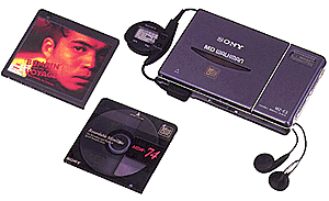 |
| Fig. 1. Example of commercial MiniDisc player. |
Before starting the CD business, many engineers engaged in the development of the CD solely for its improvement in sound quality, but after the introduction of the CD player into the market, we found out that the consumer became aware of the quick random-access characteristic of the optical disc system. In addition, the size of the 12-cm disc was easy to handle compared to that of the LP. The longer lifetime for both the media and the player strongly supported the acceptance of the CD format. The next target of development was obviously to be the rewritable CD. SONY and Philips jointly developed this system and made it a technical reality in 1989. Two different recordable CD systems were established. One is the write-once CD named CD-R and the other is the re-writable CD named CD-MO.
Sales of cassette tapes had been decreasing since 1989, and Sony felt that the compact cassette system was approaching the end of its format life. Even if recordable CD were to be accepted by the consumer, it would still be difficult to break into the portable market. Here, portable compact cassette dominated because of its strong resistance to vibration and its compactness. Clear targets for a new disc system were to overcome these weaknesses. Sony was able to achieve this by introducing a disc system called MiniDisc (MD).
Magneto-optical disc recording technology has been used for computer data storage system for several years. Based on this technology, we had developed direct overwriting technology with a similar recording density as Compact Disc. Additionally, we employed a shock-resistant memory control for portable use and applied a digital audio compression system called ATRAC (Adaptive TRansform Acoustic Coding) that enabled us to use a 64-mm disc size. Recent technological improvement of semiconductors helped to realize this technology.
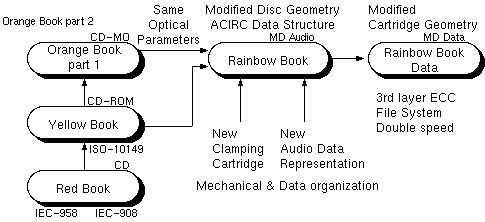 |
| Fig. 2. Technical position of MiniDisc |
Similar to the way the CD-ROM was realized, the MD Data system was developed based on audio MD. A data capacity of no less than 140 Mbytes, combined with a dedicated file structure present new possibilities to implement the MD Data disc system in several different computer systems as well as future equipment. (Fig 2).
II. System Configuration
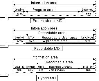 |
| Fig. 3. MiniDisc disc type and groove/pit layout. |
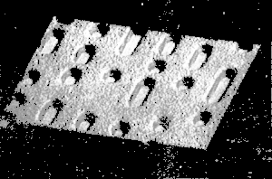 |
| Fig. 4. Pre-mastered pit. |
It is mandatory for the MD system to be able to play back these three
types of discs. This means that the MD recorder/player is equipped
with a dual-function optical pick-up for the read-out of recorded pit
patterns and the magneto-optical disc.
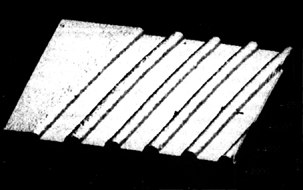 |
| Fig. 5. Recordable groove. |
The MD disc substrate is manufactured by using injection molding methods. Therefor, it is relatively easy to keep an optimal shape of the clamping area to allow for proper loading. Figure 6 shows the cross-sectional view of the disc substrate housed in the cartridge. The optical disc must be centered when it is mounted in the drive unit. As with the CD, the center is aligned using the edge of the inner circumference of the polycarbonate substrate as a reference. Constructed from simple steel, the plate is roughly positioned on the opposite side of the clamping area, to ensure proper clamping and centering. This simple method can also reduce the mechanical stress near the center area of the polycarbonate disc. This way it also helps to avoid birefringence of the polycarbonate substrate.
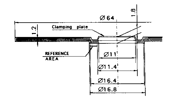 |
| Fig. 6. Cross-sectional view of MD disc. |
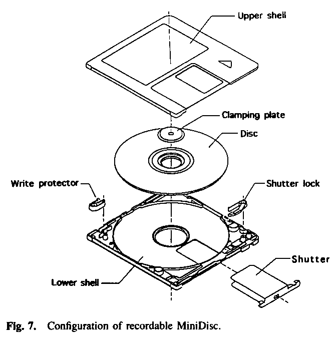 |
| Fig. 7. Configuration of recordable MiniDisc. |
The recorded signal of the premastered pits and of the recordable MD
are very similar to that of the CD. Eight-to-Fourteen Modulation (EFM)
and Cross Interleaved Reed-Solomon Code (CIRC) are employed. The
optical readout parameters of the MD disc, such as laser wavelength,
track pitch, Numerical Aperture (NA) of optical pick up, etc., are
almost the same as that of Compact Disc. (Table 1).
| Main Parameters | |
|---|---|
| Playing & recording time | max 74 minutes |
| Cartridge size | 68D x 72W x 5H mm |
| Disc Parameters | |
| Disc diameter | 64mm |
| Disc thickness | 1.2mm |
| Diameter of center hole | 11mm |
| Starting diameter of program area | 32mm |
| Starting diameter of lead in area | 29mm max |
| Track pitch | 1.6um |
| Scanning velocity | 1.2-1.4 m/sec |
| Optical Parameters | |
| Laser wave length | 780nm typ. |
| Lens NA | 0.45 typ. |
| Recording power | 2.5 - 5 mw |
| Recording strategy | Magnetic field modulation |
| Disc Type | |
| Pre mastered disc | High/low reflectivety disc (premastered pits) |
| Recordable disc | Magneto-optical disc |
| Hybrid disc | Partial premastered pit area, partial magneto-optical area |
| Audio Performance | |
| Number of channels | Stereo and Mono |
| Frequency range | 5-20,000 Hz |
| Dynamic range | 105dB |
| Wow and flutter | Quartz crystal precision |
| Signal Format | |
| Sampling frequency | 44.1 KHz |
| Coding | ATRAC (Adaptive TRansform Coding) |
| Modulation | EFM |
| Error correction system | ACIRC |
Table 1. MD System Specification.
III. Magnetic-Field Modulation Overwriting
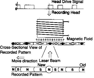 |
| Fig. 8. Magnetic-field modulation overwrite system. |
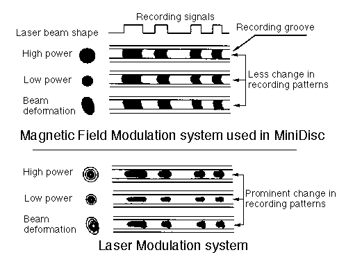 |
| Fig. 9. Comparison of recorded patterns on the disc. |
A different system altogether is used in a laser modulation system that records the signal by switching the level of the semiconductor laser power. The direction to which the magnetic fields are added is only in one direction. The area where the laser light is irradiated will be "1" and the area where no recording is made will be "0". The recording pattern will become nonsymmetrical. In addition to this, there is another problem with the laser modulation system. It is vulnerable to fluctuation in recording power. When the recording power fluctuates, the positions where the edge is started to be written or finished are easily distorted. The length of the pattern will fluctuate.
 |
| Fig. 10. Tangential skew tolerance |
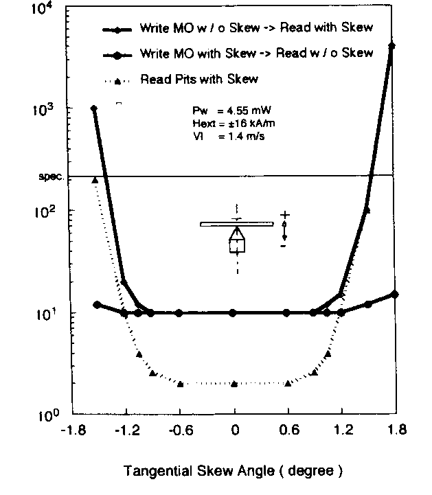
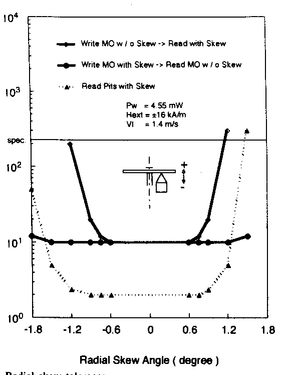
Figure 10 shows the result of the experiment. The chart shows the fluctuation of the block error rate when the disc is tilted and recorded/played back. Even when the disc is tilted +/- 1.5deg parallel to the track, the block error rate stays almost stable as long as it is not tilted at the time it is read. Figure 11 shows the data taken when the disc is tilted in the direction toward the radius. The results are almost identical to those when it is tilted parallel to the track. As mentioned so far, there are scores of advantages in the magnetic-field modulation system. These advantages hold the promise of high recording and playback reliability in the mass-production stage of the MD system.
 |
| Fig. 11. Radial skew tolerance |
- Capability of direct over-writing.
- High recording density (0.6 um/bit).
- Suitable for pit-edge modulation (EFM).
- Wide recording power margin.
- Wide margin of skew and tilt between disc and optical head.
IV. Data Structure
The MD system employs almost the same modulation and error correction code as that of the CD. Eight-to-Fourteen Modulation (EFM) and the Cross Interleave Reed-Solomon Code (CIRC) are employed as the error correction code. It is well known that the combination of the EFM and CIRC provide a high potential of error correction possibility and high recording density. The "naked" CD disc is able to provide sufficient data reliability for a long period. It shows that if the disc is enclosed in a cartridge, we can expect to increase the reliability. Hence we were strongly motivated to use the same system.
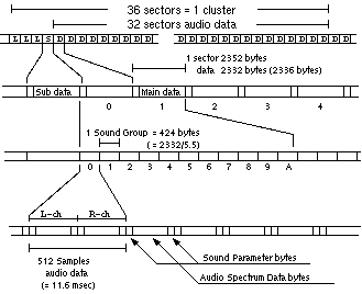
Different from the audio CD, we modified the interleave sequences slightly into a pattern suitable for keeping the interpolation between each audio sampling sequences to a continuous data sequence. We called it ACIRC (Advanced Cross Interleave Reed-Solomon Code). In case an uncorrectable error occurs during readout of the data from the MD disc, this modification helps to minimize the lack of the CD-ROM sync header. As mentioned before, MD uses compressed audio data, recorded by grouping the data into blocks. The block format is very similar to the CD-ROM mode-2 standard. In CD-ROM, we use a block address based on that of the CD's subcode address, so that we use the physical address data based on playing time. CD and CD-ROM use minutes, seconds, and frames. With MD we replaced the unit of the address from a time-base oriented one to binary-code based on frame (block) units. We call this unit (frame, block) a "sector." Because of the long interleaved ACIRC error correction code, three sectors must be used as "linking sectors." If the user changes or adds new data to the MD disc, two or three sectors for every start and end position of the new data need to be recorded.
 |
| Fig. 12. MiniDisc data configuration. |
V. ATRAC Audio Data Compression
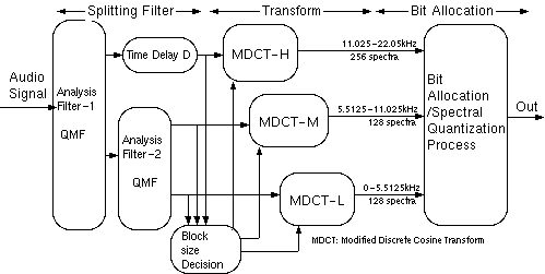
With a diameter of 64 mm, which is smaller than a CD, MiniDisc can hold only 1/5 of the data. Therefore, we need data compression of 5:1 in order to offer 74 min of playback time. A high-quality audio compression technology called ATRAC is used for MiniDisc.The ATRAC encoding process starts with the 16-bit quantization and 44.1-kHz sampled stereo audio signal. The key to ATRAC's efficiency is its unique method of analysis. ATRAC employs a nonuniform slitting in both frequency and time axes, reflecting psychoacoustic principles.
 |
| Fig. 13. Block diagram of ATRAC encoder. |
The transform block size is adaptively chosen. There are two modes, long mode: 11.6 ms for all frequency bands and short mode: 1.45 ms for the high-frequency band and 2.9 ms for mid- and low-frequency bands. Normally, the long mode is chosen to provide optimum frequency resolution. However, problems may occur during attack portions of the signal. Specifically, the quantization noise is spread over the entire MDCT block time. Just before the attack of the sound, one may hear some noise. Therefore, ATRAC automatically switches to the short mode to avoid this type of noise.
The MDCT spectral coefficients are the grouped into a Block. The spectral values are quantized by using two parameters. One is word length, another is scale factor. The scale factor defines the full-scale range of he quantization and the word length defines the resolution of the scale. Each Block Floating Unit (BFU) has the same word length and scale factor, reflecting the psychoacoustic similarity of the grouped frequencies. The scale factor is chosen from a fixed table and reflects the magnitude of the spectral coefficients in each BFU. The word length is determined by the bit allocation algorithm. For each sound frame (512 data samples) the following information is stored on disc:
- MDCT block size mode (long or short),
- word length data for each BFU,
- scale factor code for each BFU,
- quantized spectral coefficients.
The data size of each sound frame is fixed as 212 bytes. On the disc, 11 stereo sound frames are recorded every 2 sectors. In case of monaural recording, twice the amount of time can be recorded on the disc.
The bit allocation algorithm divides the available data bits between the various BFU's. ATRAC does not specify a bit allocation algorithm. The word length of each BFU is stored on the MiniDisc along with the quantized spectra, so that the decoder is independent from the allocation algorithm. This allows for an evolutionary improvement of the encoder without changing the MiniDisc format. The decoding process is divided into two steps. The decoder first reconstructs the MDCT spectral coefficients from the quantized values, by using the word length and scale factor parameters. The coefficients are transformed back into the time domain by inverse MDCT using either the long mode or the short mode as specified in the parameters. Finally, the three time-domain signals are synthesized into the output signal by QMF synthesis filters.
VI. Shock-Resistant Memory
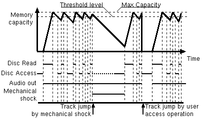
A conventional optical disc system may easily mistrack when subjected to shock and vibration. Therefore, it was believed for a long time that the magnetic-tape medium represented the best solution for outdoor use. However, car-mounted CD players are protected from external shock by mechanical suspension. In hand-held equipment, such as the Walkman, it is difficult to use mechanical suspension because it requires too much space. Therefore, we needed another way to overcome this problem.
 |
| Fig. 14. Shock resistant memory control. |
VII. MD-Data Format
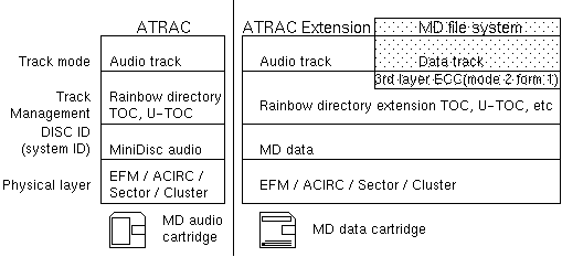
Based on the original MiniDisc audio format, the MD-Data system was developed in July 1993. The MD-Data disc and key devices (optical pickup and LSI chips) are almost the same as those of the MD audio system. Therefore, the manufacturing infrastructure of MD Data is commonly used with that of MD Audio. Actually, it is similar to the way CD-ROM is manufactured. The MD-Data disc has approx. 140-Mbyte data capacity (Fig. 15). By featuring a variation of disc type (pre-mastered disc/read-only disc, recordable, and hybrid disc) and compact size, the MD-Data system is expected to be a new standard in data storage and publishing media systems.
 |
| Fig. 15. Format comparison between MD and MD-data. |
| Main Parameters | |
|---|---|
| Capacity | 140 Megabytes |
| Cartridge size | 68D x 72W x 5H mm |
| Normal data transfer rate | approx 150Kbyte/s (300Kbyte/sec double speed) |
| Disc Parameters | |
| Disc diameter | 64mm |
| Disc thickness | 1.2mm |
| Diameter of center hole | 11mm |
| Starting diameter of program area | 32mm |
| Starting diameter of lead in area | 29mm max |
| Track pitch | 1.6um |
| Scanning velocity | 1.2 m/sec or 2.4 m/sec |
| Optical Parameters | |
| Laser wave length | 780nm typ. |
| Lens NA | 0.45 typ. |
| Recording power | 2.5 - 5 mw |
| Recording strategy | Magnetic field modulation |
| Disc Type | |
| Pre mastered disc | High/low reflectivety disc (premastered pits) |
| Recordable disc | Magneto-optical disc |
| Hybrid disc | Partial premastered pit area, partial magneto-optical area |
| Physical Data Structure | |
| Modulation | EFM |
| Error correction system | ACIRC |
| Additional layred ECC | selectable |
| Sector size | 2048 or 2336 bytes |
| Cluster size | 32 sectors |
| Maximum cluster number | approx 2200 |
| Maximum sector number | approx 70000 |
| File Structure | MD data File System |
| Block size | 2kbyte - 64kbyte |
Table 2. MD Data Specification.
The MD-Data volume and file structure was developed to cope with the MD's physical limitations. The data track, similar to the music track on the MD Audio, is defined in the TOC and the U-TOC. The first cluster is used for a boot cluster, and a further 16 clusters are used for the Volume Management Area (VMA), where all files and directory management information are gathered. Because the VMA is physically centralized and is usually cached in semiconductor memory, the number of accesses and rewriting operations are minimized. Even more, considering the physical cluster actually means a minimum rewriting unit, the MD-Data file system can manage a logical block size ranging from 2 to 64 kbytes. These block sizes are uniquely selected depending on the application by the user. The file system can also support a hierarchical directory structure, short- and long-file names, additional information, etc. It allows easy connection of MD Data to various host systems and allows for media exchanges between different systems (Table 2).
VIII. Conclusion
Considering the many advantages of the disc media, we can expect that MiniDisc will replace the Compact Cassette in the near future. When this occurs, we are certain that the MiniDisc player unit will be smaller than the current Walkman Compact Cassette player, largely due to the MD's cartridge size. In order to realize this, the key issue is to downsize the relatively bulky electronics into silicon. The key issue here is the huge number of gates and the total number of LSI chips and this will soon be overcome by the progress in LSI design rules. At that time we can also expect broad application of the MD-Data format.References
- K. Tutui, H. Suzuki, O. Shimoyoshi, M. Sonohara, K. Akagiri, and R. M. Heddie, "ATRAC: Adaptive transform acoustic coding for MiniDisc," presented at the Audio Engineering Society 93rd Conv., Oct. 1992.
- K. Tsurushima, T. Yoshida, K. Fujiie, K. Akagiri, and D. H. Kawakami, "MiniDisc: A disc-based digital recording format for portable audio applications," presented at the Audio Engineering Society 93rd Conv., Oct. 1992.
- R. Ando, K. Fujiie, T. Yoshida, K. Watanabe, and T. Nagai, "High density magneto-optical disk capable of overwriting by magnetic field modulation," IEEE Translation of J. Magn. in Japan, vol. 3, no. 8, Aug. 1988.
- T. Yoshida, "Optical recording system in MiniDisc," in Proc, ODS '93. pp. 33-35.
- Std. ISO-10149, "Compact Disc Read Only System Description," Int. Standardization Org., Geneva, Switzerland.
About the Author
Tadao Yoshida received the Bachelor of Arts degree in electronics communication from Waseda University, Tokyo, Japan, in 1973. Currently, he is the General Manager of the Advanced Development Laboratory, Sony Corporation, Tokyo. At Sony, he has helped to develop the Compact Disc System, Magneto-Optical Compact Disc (CD-MO) System, the Global Positioning System (GPS), and the Applied Car Navigation system.Translations: